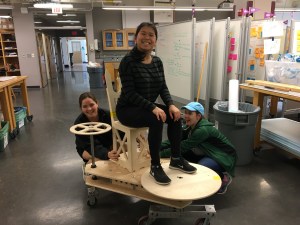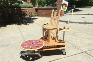
This human-powered omni-directional vehicle features a unique design that places an emphasis on simplicity and creativity. Our team was motivated by a desire to produce a lightweight, low-cost vehicle that was adaptable and easy to assemble without sacrificing performance. To accomplish this, the group developed an innovative drive mechanism. Inspired by the RipStik skateboard, this drive mechanism consists of a caster board, a two-wheeled platform which the user pivot and wiggles back-and-forth with their feet to generate motion in a given direction. To steer the vehicle, the caster board mechanism can be oriented in any direction. Overall, the design effectively achieves omni-directionality while preserving the ability to maintain momentum while turning. The vehicle was unique among its competitors in that it did not utilize a direct-drive mechanism for propulsion. This enabled our machine to place first for lightest weight and lowest cost (and our team got the ‘best team dynamics’ award).
III. Theory and Rationale Behind Design
VI. Analysis and Testing (FEA and Physical)
I. Challenge:
Challenge: Omni Triathlon Race – The goal of this project is to design a human powered vehicle which is both omnidirectional and zero turn radius. Omni-directionality means that a vehicle can move in any direction while facing in any direction.
The Three Races:
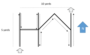
- Omni-Challenge: Navigate a maze while facing only one direction
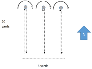
- Drag Race: 20 yards. There and back.
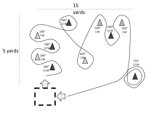
- Gymkhana: race through a cone course as fast as possible
Deliverables:
-
- Complete CAD documentation
- Functional omnidirectional vehicle
- FEA simulations of critical components
- Final Report
II. Design:
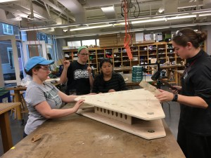
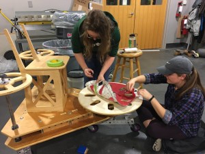
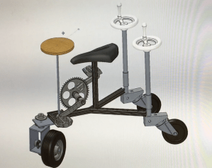
Our design methodology started with rough sketches and brainstorming of individual modules, such as the chassis, steering, powering, and brakes, that would come together to meet the design requirements. The ideas were then shared and discussed with the entire group, as well as Professor Diamond, the TA’s, shop instructors and classmates. From there, we created detailed designs through rapid prototyping and SolidWorks modeling. We started with a pedal powered design because we believed it would be the best way to harness the power of our legs. However, we quickly transitioned into our final wiggle powered design, drawn by the simplicity and uniqueness of the mechanism. Through testing modules on a small scale and many iterations of the entire vehicle assembly on SolidWorks, we were able to finalize the optimal layout and finer details prior to physical creation of the vehicle. Due to our preparation and robust SolidWorks design, we were able to machine and assemble most of the parts once, requiring only minor adjustments to some connection pieces and ergonomic features after the initial prototype. The following provides a detailed description of the creation and analysis of our omni-directional vehicle.
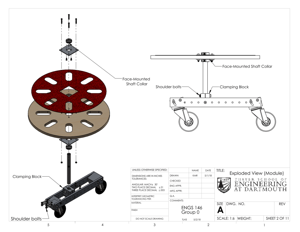
Caster-Drive
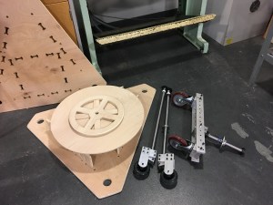
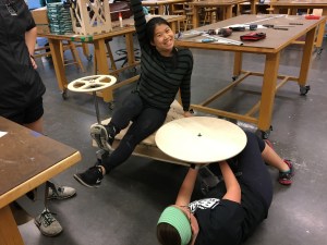
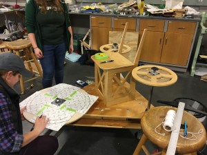
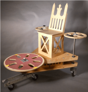
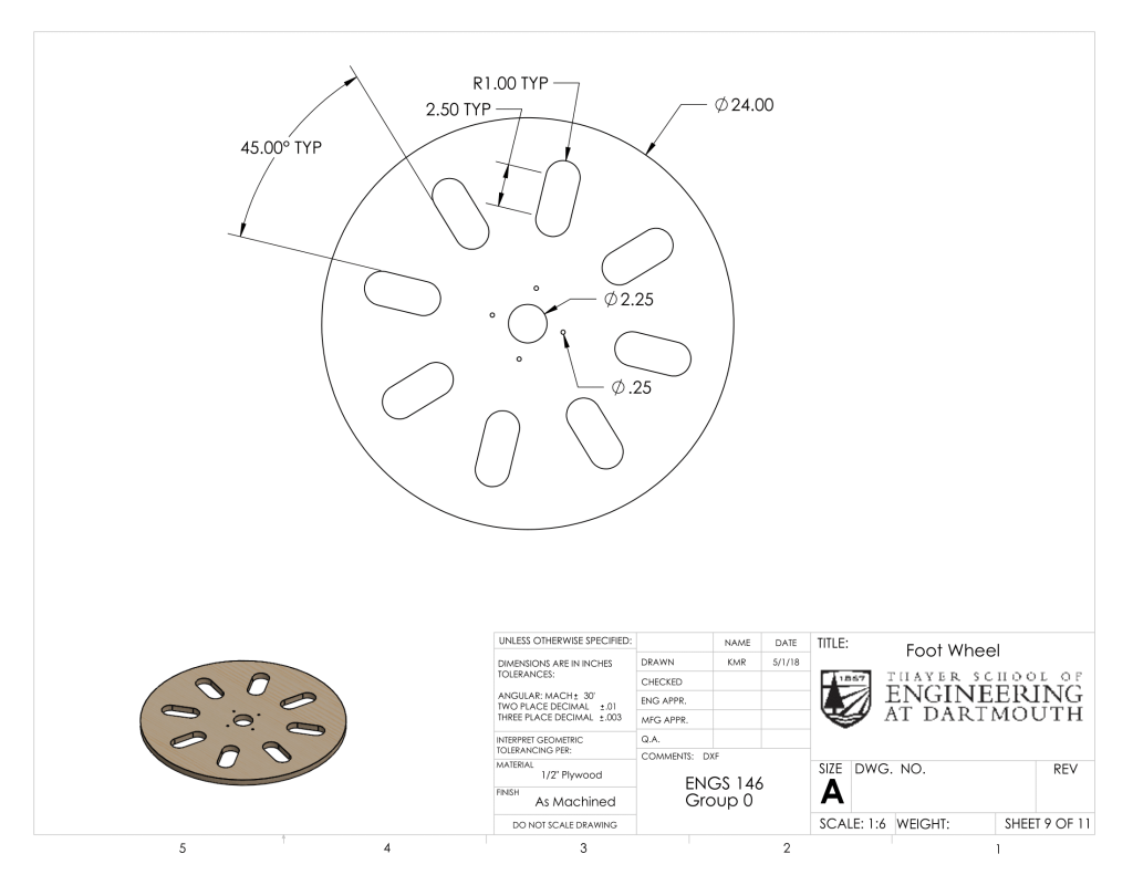
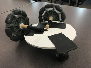
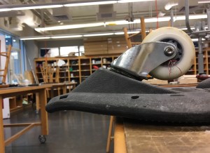
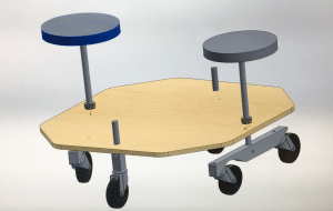
The caster drive module consists of the foot wheel and caster board, including the shaft and hardware that connect them. A rider uses his or her feet to wiggle the plywood foot wheel back and forth. A shaft is mounted to both the foot wheel and the mid-block of the caster board, so that this motion also causes the caster board to wiggle. The caster wheels, which are mounted to the caster board at variable angles, then produce a fishtailing motion which propels the machine forwards. The mid-block’s mounting is also adjustable, so that its positioning can be altered for different performance challenges (i.e. optimizing speed, maneuverability, zero- turn capability, etc.). The foot wheel features cutouts and adhesive grip tape to make it easier for a rider to move it back and forth.
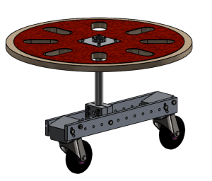
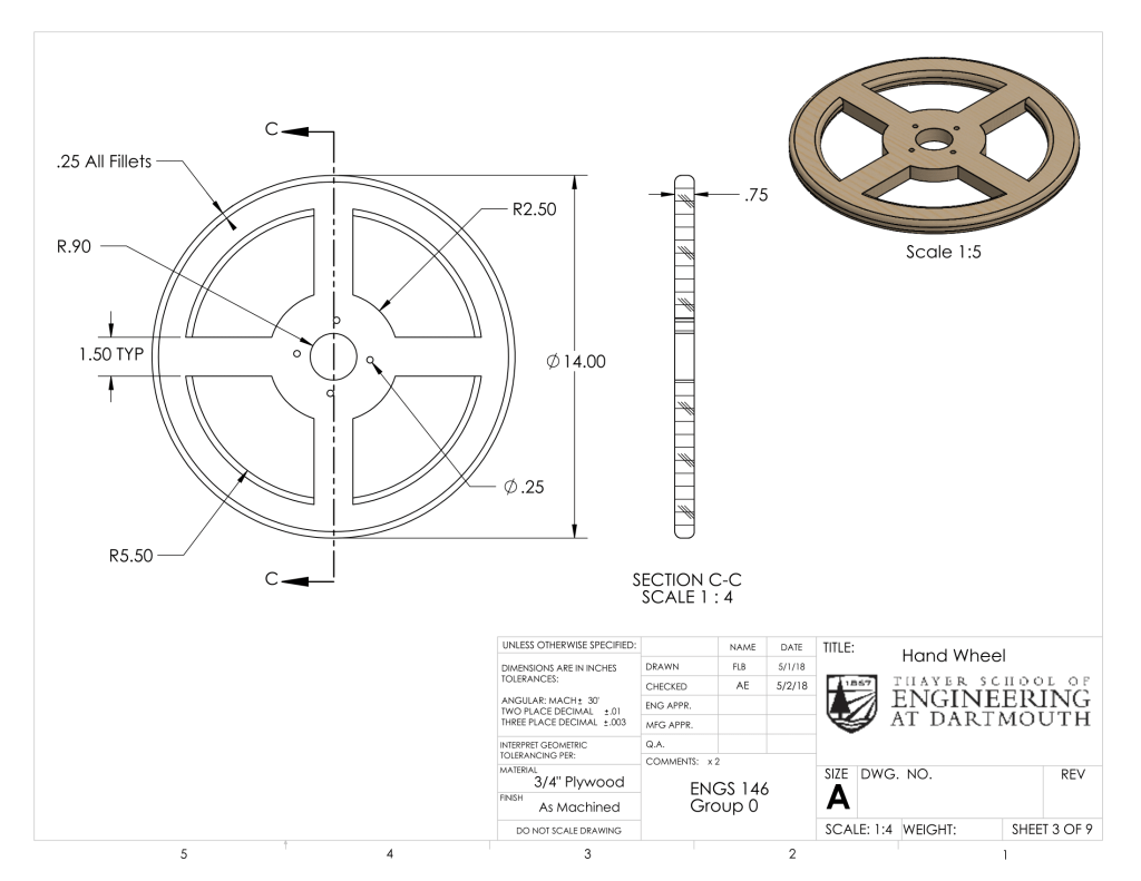
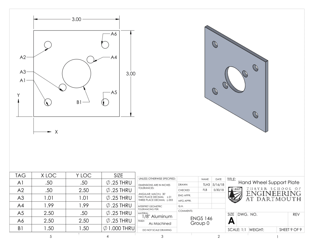
Hand Wheel
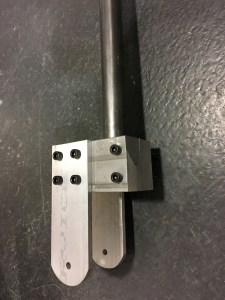
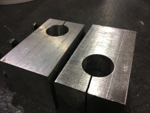
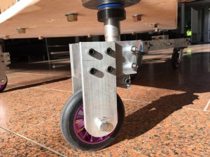
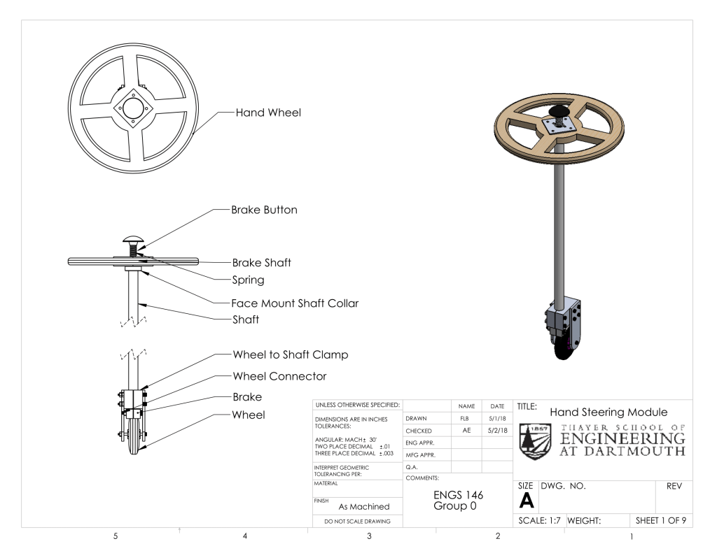
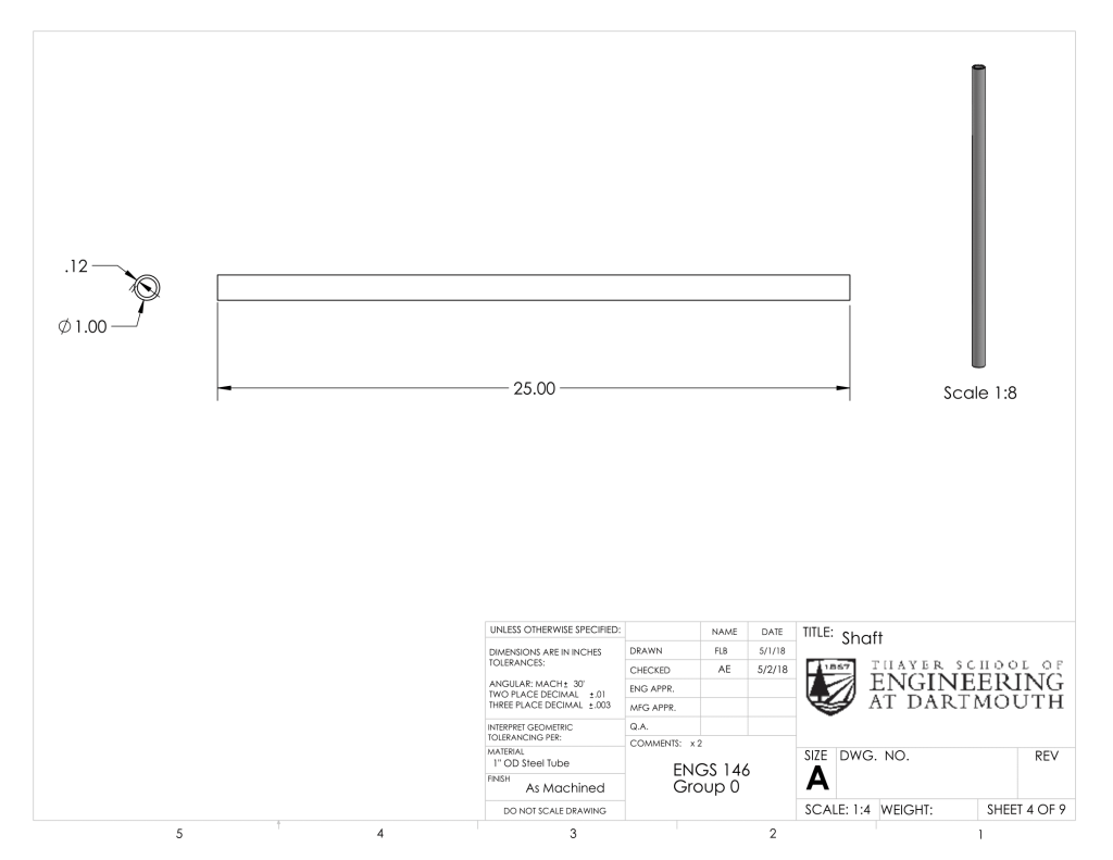
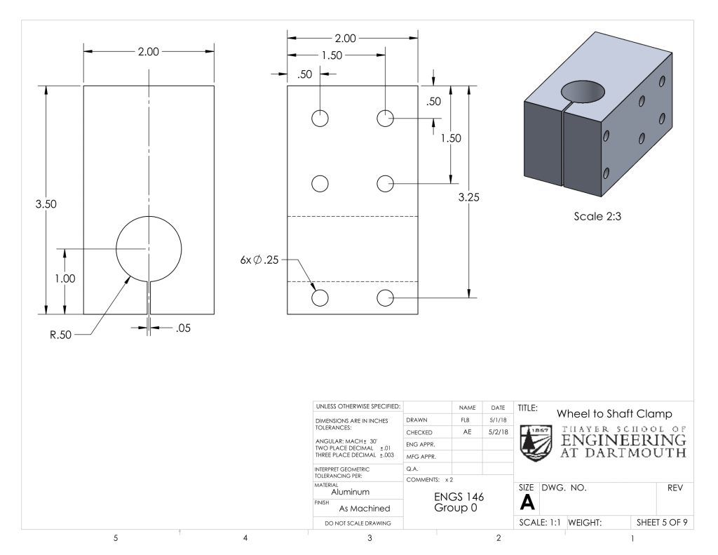
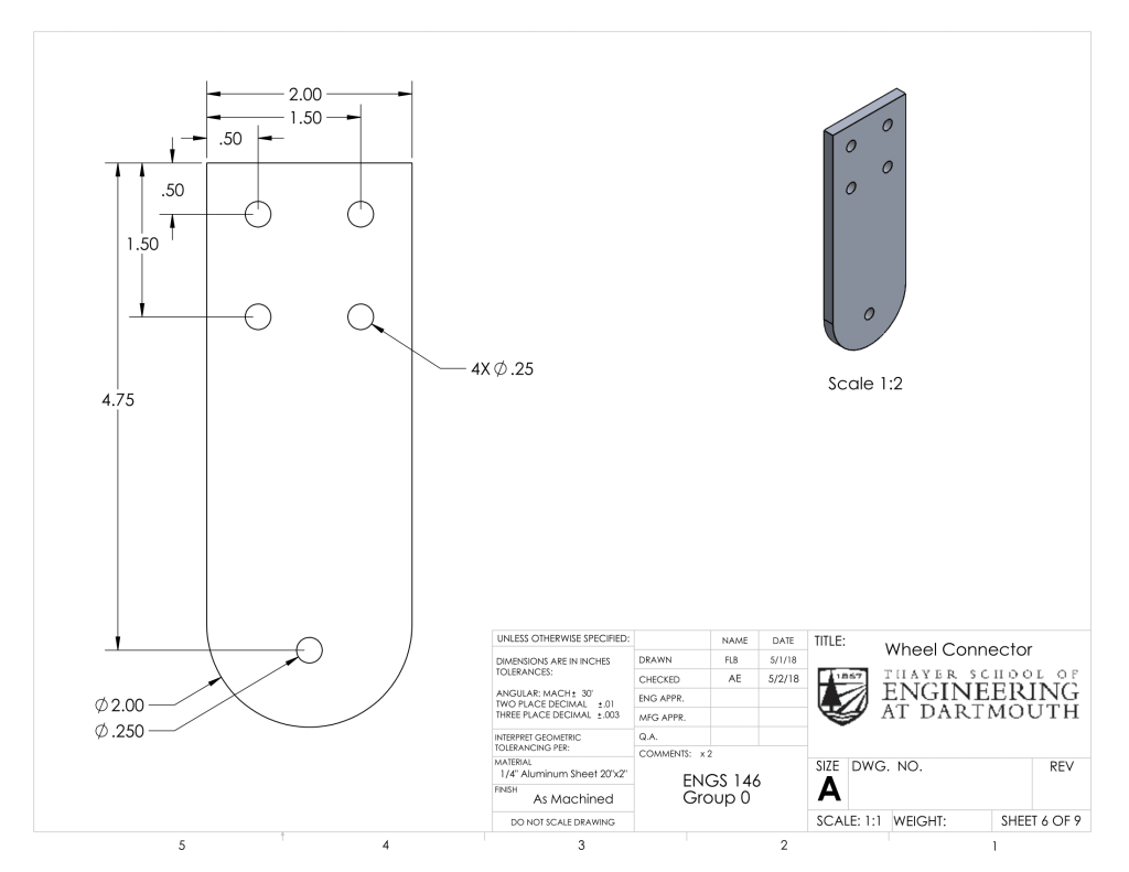
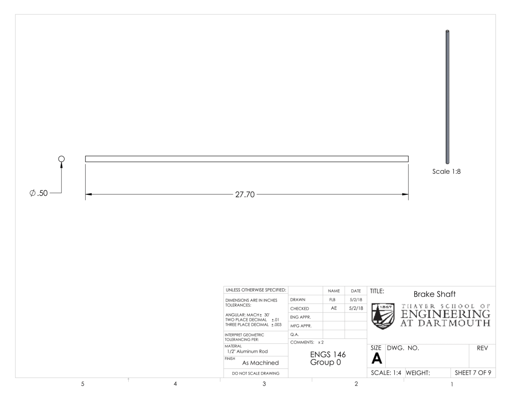
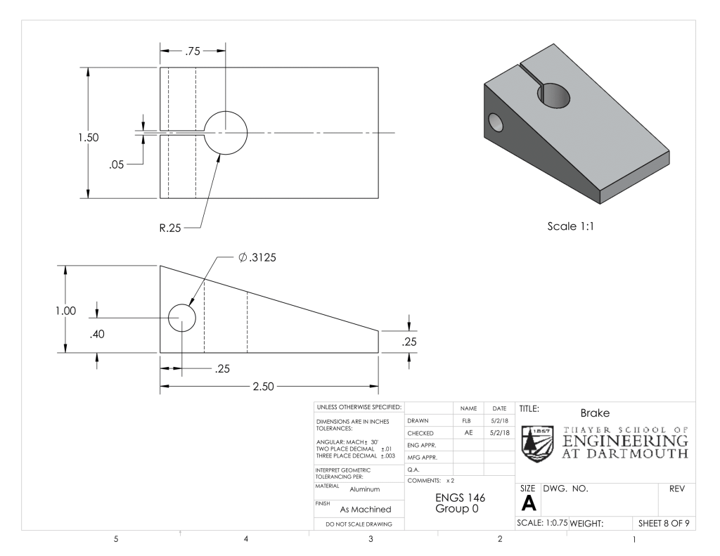
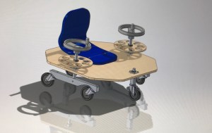
The hand wheel module consists of a plywood steering wheel (Hand Wheels) mounted onto a 1-inch steel shaft which runs down, through the chassis, and clamps into a block (Wheel to Shaft Clamp) which is bolted to a wheel connector panel on either side. A bolt runs through the bottom holes of these wheel connectors, supporting a 110mm scooter wheel. If left alone, these wheels will trail in the direction that the machine is moving. They can also be turned using the hand wheels to achieve a sharp change in direction, including a zero-radius 360 degree turn. This module also includes the braking mechanism. This mechanism features aluminum wedge-shaped brakes, which clamp onto a 1/2″ steel shaft. This shaft runs up through the hollow center of the larger steel shaft. A mushroom cap is attached to its top, and a compression-spring rests between this cap and the top of the 1″ steel shaft, supported by a Delrin insert. When a rider presses down on the mushroom button, the wedged brake piece comes into contact with the wheel, impeding its motion instantly.

Chassis
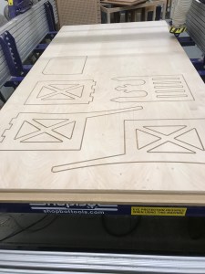
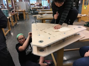
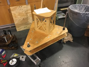
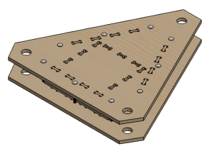
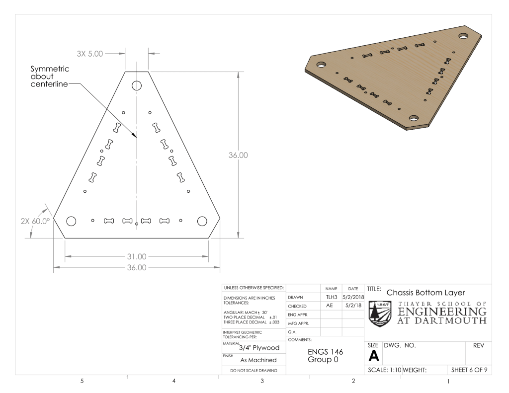
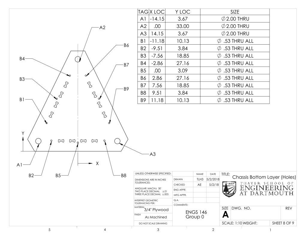
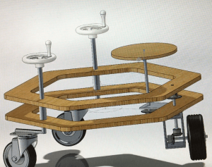
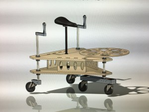
Our machine has a two-layered chassis. The rationale for the two layers was to have multiple points of contact between the chassis and each of the shafts to provide lateral support. The layers are connected by tabbed vertical support pieces and carriage bolts. Flanged bearings are press-fit into three holes in each chassis layer – one in the front, and one in each rear corner. The three shafts run through these bearings. The top chassis has dog-bone shaped cutouts for the tabs of the chair to fit into, and both layers feature this type of cutouts for the tabs of the vertical supports. Each chassis layer was cut out of 3/4″-thick plywood using the ShopBot.
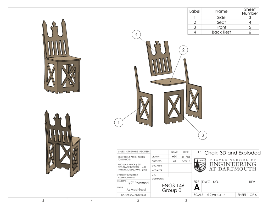
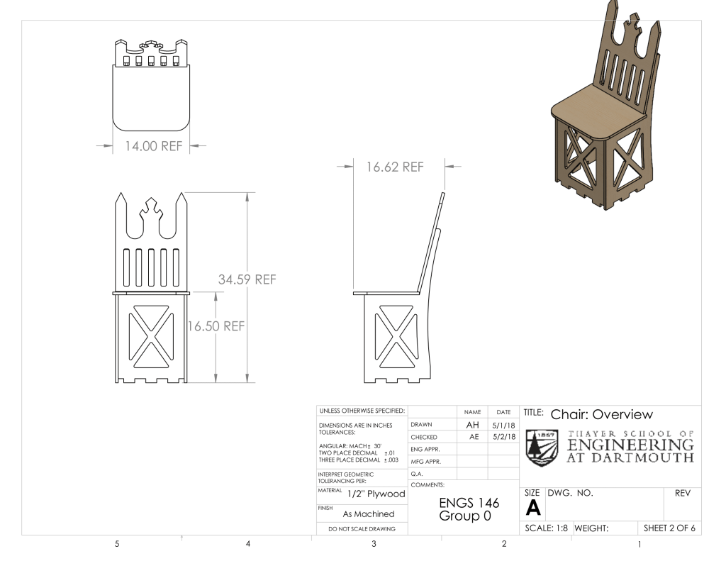
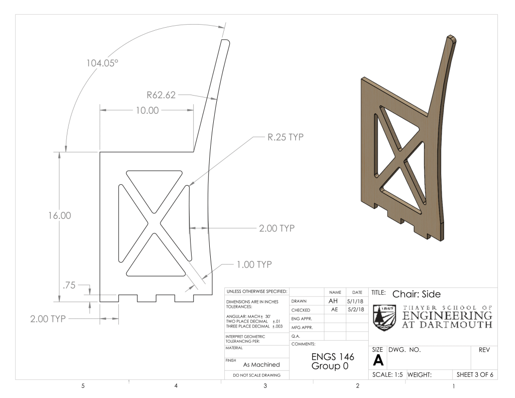
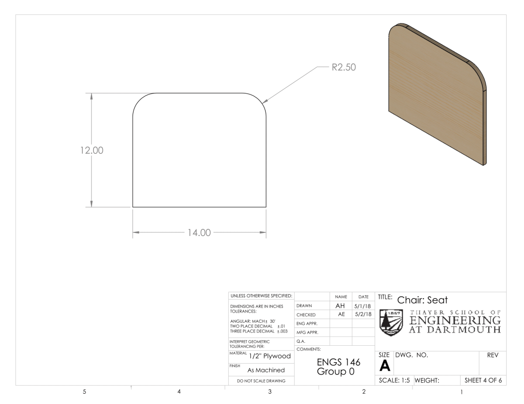
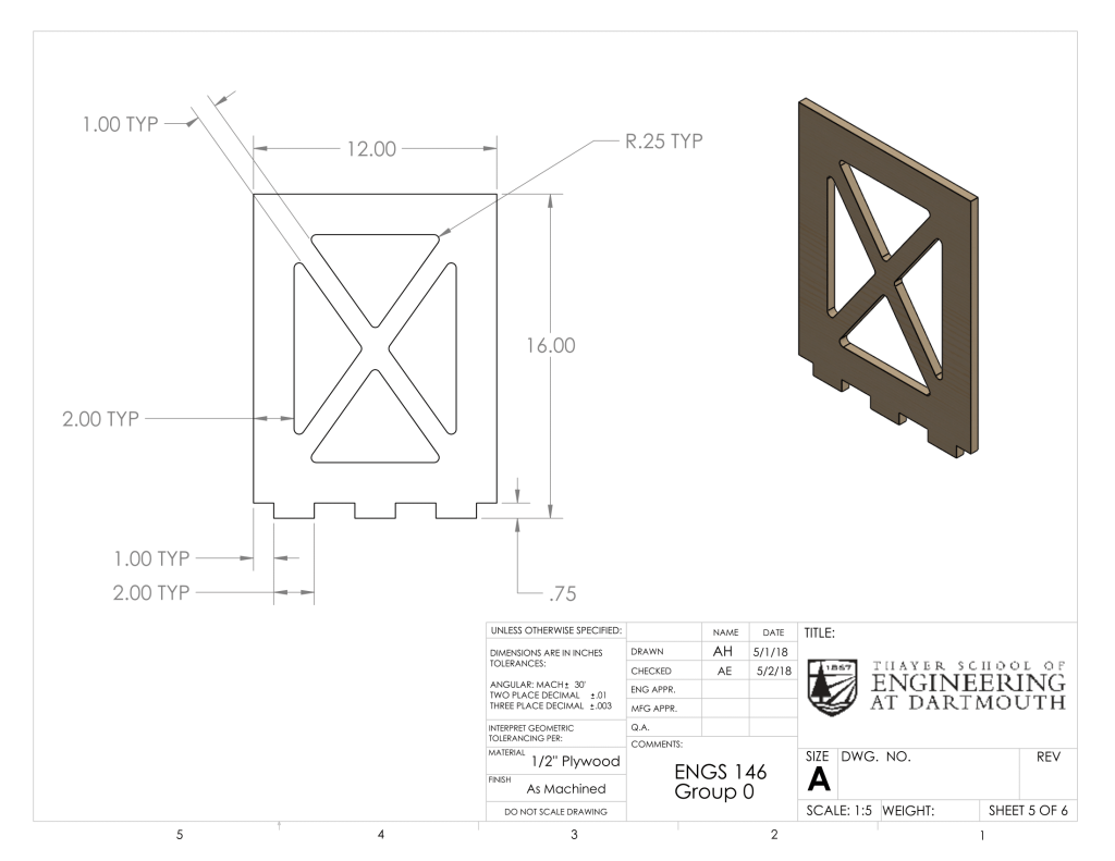
Chair
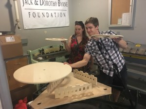
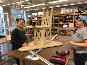
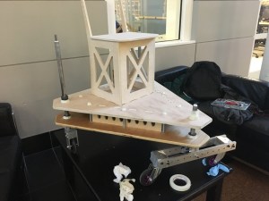
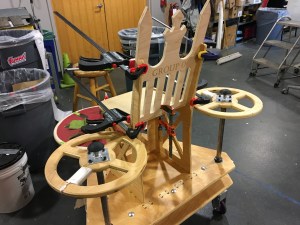
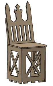
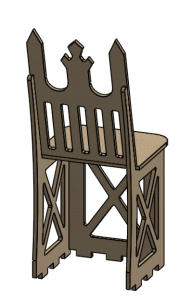
The chair of our machine is both functional and decorative. It is made entirely of plywood and features a flat seat resting on three vertical panels which have tabs that fit into slots in the top chassis. These three panels face forwards, left, and right and have triangular cutouts for light-weighting. The back of the seat is slightly tilted for rider comfort, and it is shaped like a throne for maximized commercial viability. The pointed tips of the backrest can be used to impale one’s enemies (only in self-defense), but for safety purposes we covered them with ping pong balls.
Back to Top
III. Theory and Rationale Behind Design:
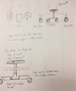
During the initial stages of our design development, we considered two primary human power sources for driving our omni-directional vehicle – hand power and foot power. We decided to pursue a foot-powered design to allow for greater power while freeing our hands to operate a steering module, granting us the ability to navigate with precision. We considered incorporating a pneumatic or hydraulic mechanism for amplifying our human power, but turned away from these ideas in an effort to maintain simplicity and elegance in our design.
Having settled on a foot-powered vehicle, we conducted research and brainstorming sessions to determine the optimal locomotive mechanism. The strongest candidates to emerge from these sessions were pedal-power and wiggle-power, which drew their inspirations from bicycles and a type of skateboard known as a caster board, respectively. While pedal-power was an attractive option, we had difficulty establishing layout for a pedal-powered vehicle that fit within the specified size constraints. Additionally, the bicycle design presented budgetary concerns – our initial cost estimates suggested that a pedal-powered design would exceed the preliminary budget of $1,000. These facts, combined with a desire to maintain simplicity in our design, led us to pursue a wiggle-powered solution.
While we had all witnessed the speed and maneuverability of caster boards, the exact mechanisms underlying their motion remained abstract to us. To gain a better intuition for this motion, we sought out video footage, consulted research papers, and even acquired a caster board and learned how to ride it. Standard caster boards feature two foot platforms connected by a torsional spring. Beneath each platform is an angled, trailing caster. Caster boards are ridden so that the wheels are aligned linearly, and wiggling back-and-forth generates a resultant forward motion as the two angled caster wheels move opposite to one another. The motion of the caster board is “governed by both nonholonomic [path-dependent] velocity constraints and momentum conservation” [1]. When compared to a traditional two-wheel drive vehicle, as we came to experience, the caster board exhibits “greater maneuverability and potentially higher efficiency at the expense of stability” [1]. The twisting of the torsional spring allowed the rider to maintain balance and have greater control over their direction of travel, but was not necessary for the caster board to produce forward motion.
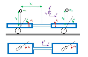
Diagram of a typical caster board
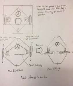
Our early designs featured two of these caster boards, with the idea that one would be controlled with each foot. This led us to adopt a square design for our chassis. However, we were concerned about the degree of coordination that would be required to operate a vehicle that requires four limbs to work independently. We modified our design to feature a single caster board module to power our vehicle’s motion in any direction, and two hand-steering modules to orient the chassis body. This decision informed our chassis layout, leading us to adopt a triangular configuration to maximize the distance between these three modules, and thus maximize the stability of our chassis.
While the locomotive mechanism underwent a considerable degree of iteration, our hand-steering module remained relatively unchanged throughout the process. The module consisted of a 25-inch steel tube with a trailing caster at the bottom and a steering wheel at the top. These wheels could be used to control the orientation of the chassis. Because we did not utilize a direct-drive mechanism and our vehicle relied so much on coasting, drifting, and transferring momentum, we also sought to incorporate a braking mechanism. This was accomplished by running a shaft concentrically through the hand-steering module tube and down to the trailing caster. An aluminum block was clamped to the brake shaft, and a spring held the brake mechanism above the wheel. To brake, the driver simply depressed a button to compress the spring and make the brake contact the wheel. This allowed our vehicle to stop very quickly, and different braking pressures could be applied to improve navigation.
IV. Problems Encountered:
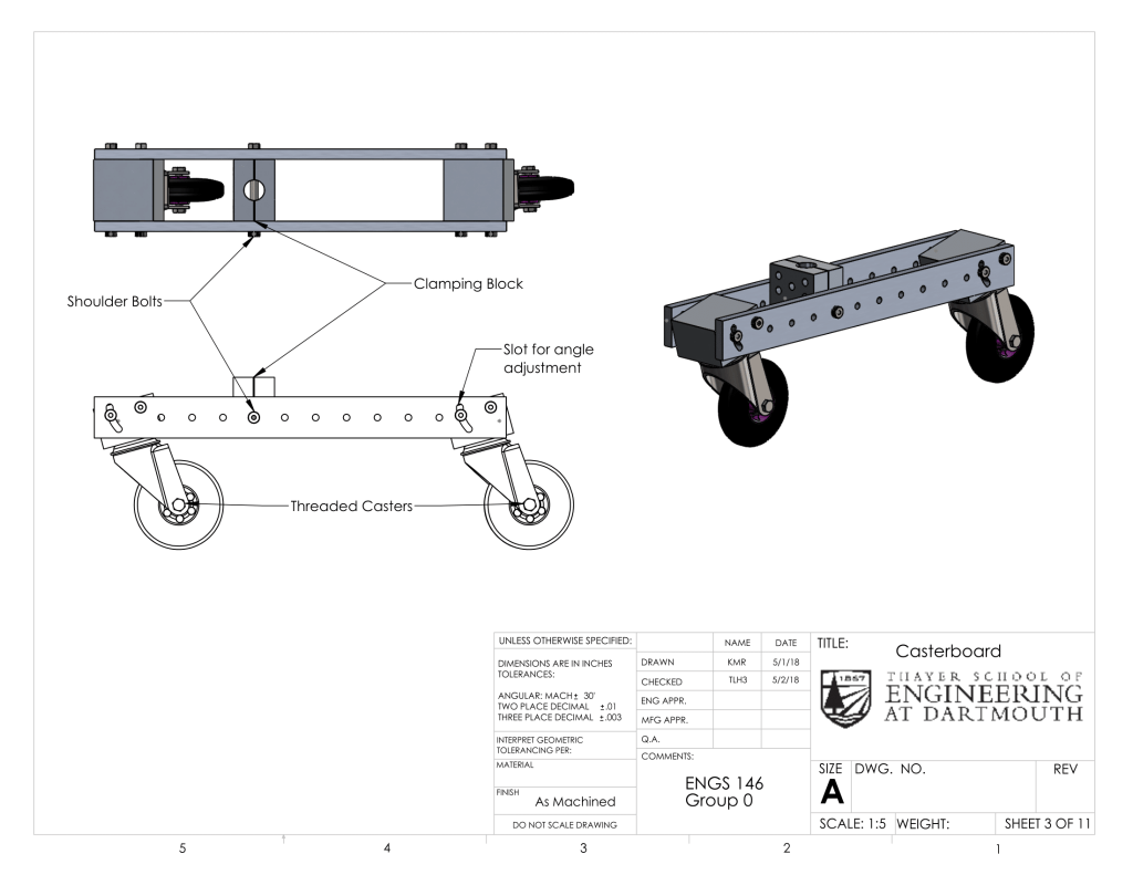
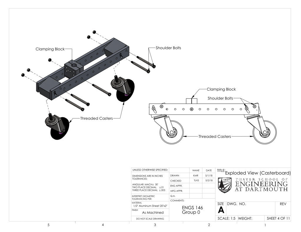
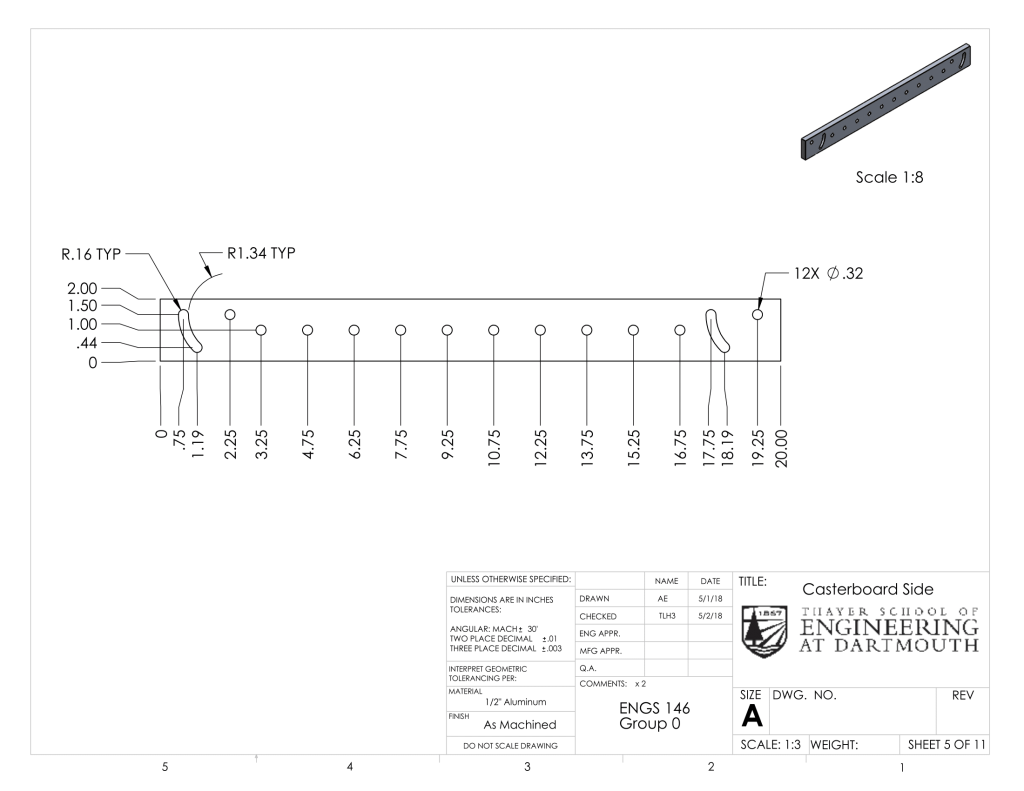
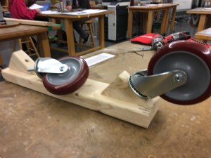
The practical design of an effective wiggle powered vehicle proved challenging even after understanding the theory behind the mechanism. Due to the complex physics of wiggling, it was difficult to predict the exact motion and power output through calculations or SolidWorks motion simulations. The optimal angle of the caster wheels and position of the midpoint of swivel were difficult to determine due to the complexity of modeling wiggling motion and calculating the effects of those aspects on the overall power delivered to the vehicle. Since caster boards were difficult to simulate and making multiple parts out of metal would be time consuming and expensive, we decided to create a caster board with adjustable wheel angles and pivot point. These were achieved by creating separate wheel blocks, mid-block, and sideboards. The two sideboards feature holes regularly patterned along the length where the mid-block could be moved and attached, changing the pivot point. At the ends, there is a pivot hole and a slot where the wheel block can be attached and the angle can be varied by securing the bolt to a specific point in the slot. Please see below section for drawings of the caster board. Creating an adjustable caster board allowed for simple adjustment and experimentation to achieve the fastest possible configuration post-manufacture. After building the vehicle, we were able to determine and implement the best wheel angle and pivot point for speed.
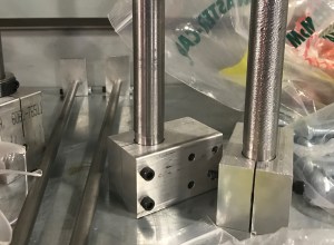
The steel shafts we purchased had a tolerance of 0.004. The shafts we received had a larger diameter than our shaft collars and bearings. Thus, we had to turn down the shafts on the lathe and test the fit of the shaft collars and bearings often. This was challenging because the shaft rattled as we turned it down due to its length. Since we did not want to remove too much material such that the shaft collars were no longer a tight fit, we opted to sand the metal shafts when we got closer to the diameter we wanted. We do not recommend sanding metal, as it takes a long time. Though it was a long process, we were able to press fit the shaft collars, bearings, and our own pocketed holes on the shaft.
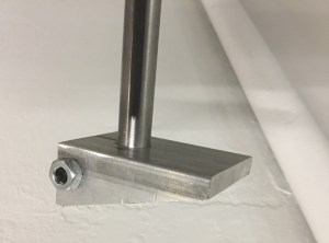
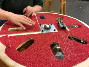
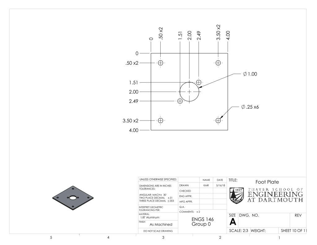
Another problem that we encountered was the bolts of the face-mounted shaft collar shearing through the wooden foot wheel in our first prototype. This inhibited our ability to apply torque to the foot wheel without widening the bolt holes in the wheel and eventually breaking the wheel. To mitigate this problem, we created 1/8″-thick aluminum plates for the top and bottom of the foot wheel. These plates contained two bolt holes for the shaft collar, four holes to mount it to the wheel, and a pocket in the middle for the shaft to go through. The top and bottom plate were then bolted tightly, clamping the wheel so that the friction between the metal and the wood would allow the shaft to turn the wheel without the bolts shearing into the wheel. The same improvement was applied to the hand wheels, which also experience large torques.
Closer to race day, we noticed that when the foot wheel was turned too fast, it would move independently from the caster board. This was especially cause for concern because turning the foot wheel 180 degrees fast was our mechanism for switching from forward to backward movement on the omni-challenge. After tightening the shaft collars, this issue was not resolved. We finally realized that the shaft was turning in the mid-block on the caster board. When the bolts in the clamp mechanism of the mid-block were tightened, the caster board turned securely when we turned the foot wheel and we were ready for race day.
V. Innovations and Advantages:
Human-powered omni-directional vehicles represent a unique and compelling design challenge. Our investigation of the state-of-the art omni-directional vehicles yielded a number of designs that feature motors, omni-wheels, and other mechanisms. Few sophisticated patents exist for human-powered omni-directional vehicles; this design challenge thus lead to a number of innovative solutions throughout the class. Even among the class’s creative solutions, our design was unconventional. While direct drive solutions such as pedals and hand cranks seemed like the most intuitive mechanisms for powering the vehicle, we decided to examine other, nontraditional mechanisms. During this search, we came across the Ripstik skateboard and sought to apply this type of motion as the driving force of the vehicle.
The key advantage of this non-direct driving mechanism relates to maneuverability. The Ripstik-inspired caster board gains its speed while oscillating back and forth and can then maintain its momentum while turning, consequently enabling quick transitions. This is a huge advantage in challenges such as the gymkhana, where quick transitions and changing orientation are crucial – provided the terrain does not present any complications. Provided that our vehicle can maintain speed, even while turning, we needed to design a brake mechanism.
Since we did not have a direct-drive mechanism, we machined spring loaded brake shafts for each of our hand-steering modules. This method of braking causes no stress to the vehicle’s drive system, contrary to vehicles that use direct drive (which in order to stop, often require the application of significant torque on the mechanism). Our vehicle is able to coast and stop quickly, which is a major advantage in the omni-challenge and the drag race. The braking mechanism also allows the vehicle to make more precise maneuvers. Our caster board-driven design represents a unique solution to the challenge of human-powered omni-directional vehicles.
VI. Analysis and Testing (FEA and Physical):
Weight Loading on Wheel Axle Bolts
To determine if our machine would hold enough weight, we performed Finite Element Analysis on the Wheel Connector subassembly using a SolidWorks Static Motion Study. We wanted to make sure that the wheels of our vehicle could support the weight of the machine itself and of a rider. According to the mass properties feature in SolidWorks, our machine weighs 79.67 lb. We assumed, estimating conservatively, that the heaviest member in our group might weigh 200 lb after an enormous Foco lunch. Thus, rounding up, the total weight that would be distributed over the four wheels of our vehicle is about 300 lb, or 1334.5 N of force.
Since the total weight of our machine and rider is distributed over three shafts (one from each of the two hand wheels, and one that supports the caster board), we assumed that each of the rear wheels carries one third of this total weight. In ideal conditions, it likely carries less, since there are four wheels total. However, in the event that our machine is on uneven ground or tips in one direction, all of its weight and that of the rider would be resting on one wheel. Thus, to be conservative, we decided to apply the full load of 1,1334.5 N to a single wheel mount module for this round of FEA testing.
In the simulation, the iron-oxide covered alloy steel bolt that supports the wheel is fixed. The 1,334.5 N load is applied downward on the surface of the wheel mount block’s central hole, to represent the downward force acting on the shaft which is mounted inside this hole. A curvature mesh is applied to allow for the cylindrical face of the bolt in the assembly. The wheel is suppressed for simplicity and to avoid interference errors. See simulation results in the below figure.
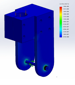
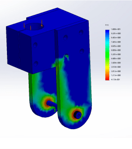
Left: SolidWorks Static Loading Study of Wheel Connector Subassembly: Stress
Right: SolidWorks Static Loading Study of Wheel Connector Subassembly: Factor of Safety
The simulation shows that the maximum stress in this subassembly is 199.8 MPa, occurring on the alloy steel bolt where it rests in the hole of the wheel mount part. This value is substantially less than the yield stress of alloy steel, which is 620 MPa according to SolidWorks. The results of this static study yielded a minimum factor of safety of 4.139. This gave us great confidence in our design, as even in the worst case scenario, when a single wheel is holding the entire weight of the machine and its rider, the Wheel Connector subassembly is 4 times as strong as it needs to be.
Driver Loading on Chassis
To determine the structural stability of the chassis, we performed a Finite Element Analysis on the chassis assembly. We applied a 200-lb load over the surface to represent the rider, and fixed the chassis assembly at each of the shaft and bolt holes. Our chassis design was fairly robust; for this load, it featured a minimum factor of safety of 24. Even in cases where forces are amplified due to bumps or uneven loading, the chassis should not experience any loads that approach its yield stress. With this loading, the maximum stress on the assembly was 1.523 MPa; this was significantly lower than the yield stress of the material, 36.5 MPA [2]
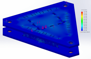
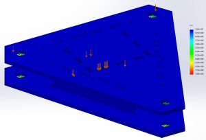
Left: SolidWorks Static Loading Study of Chassis: Stress
Right: SolidWorks Static Loading Study of Chassis: Factor of Safety
Driver Loading on Seat
To ascertain that the seat could handle the weight of the driver, an FEA analysis was done on the seat of the chair with a weight of 200 lbf, just over the weight of any of our teammates. We decided that a minimum factor of safety was 5. Though this might seem high, we have to account for anyone in the future riding the vehicle weighing more, as well as any impulses caused by jostling or bouncing while riding. Fortunately the FEA showed a FOS of 9.472, way above our threshold of 5. The loading was put directly on the seat, to account for the scenario of not leaning back on the chair at all, which we found to be the most common scenario. The sides of the tabs were modeled as fixed connections because they were both glued and given an interference fit.
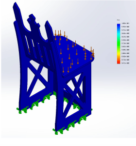
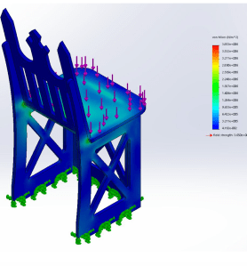
Left: SolidWorks Static Loading Study of Chair: Stress
Right: SolidWorks Static Loading Study of Chair: Factor of Safety
Caster Board Motion Analysis
To gain a better understanding of the physical dynamics of our caster board design, we performed a SolidWorks Motion Analysis. Isolating the caster drive module and holding the shaft fixed so that the caster wheels contacted a surface, we applied an oscillatory rotary motion to the foot wheel. The motion was defined according to the equation:
10*sin(t/2)
This equation was selected to produce an oscillating motion of 10 degrees on either side of the caster drive module’s original angular position, with the caster module returning to its original angular position every 2 seconds. Solid body contact was defined between each of the caster wheels and the terrain, with the material set to ‘Rubber (Dry)’ for both surfaces to ensure a high coefficient of friction. Gravity was enabled, and the motion analysis was run for 5 seconds. The angular displacement of the foot wheel, front caster, and rear caster were recorded, and the information is shown below in the below figures.
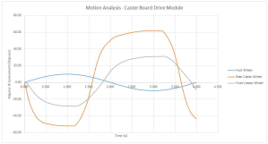
Motion analysis for the caster board drive module (angular displacement vs. time)
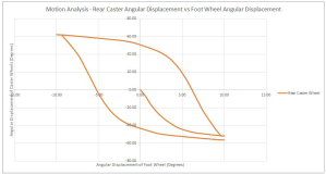
Motion analysis for the rear caster (angular displacement vs. angular displacement)
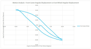
Motion analysis for the front caster (angular displacement vs. angular displacement)
As these graphs demonstrate, the rear caster achieves a significantly higher angular displacement than the front caster, for the same angular displacement of the foot wheel. This is likely due to the geometry of the caster board in this simulation: the mid-block is positioned closer to the front wheel than the back wheel, so the rear caster wheel undergoes a greater displacement than the front caster wheel as the foot wheel rotates. Thus, more of the energy from rotation is lost as the rear caster wheel orients itself away from the direction of travel. This was confirmed by our physical testing – placing the mid-block closer to the front caster resulted in less forward propulsion for a given rotation of the foot wheel. To increase the speed of our design, we chose to position the mid-block closer to the rear caster. This reduced the angular displacement of the rear caster wheel, enabling more energy from the rotation of the foot wheel to be transferred into forward motion.
VII. Conclusions:
Overall the final vehicle performed as expected. The caster board gave a strong propulsion in any direction it faced, while the two hand wheels helped us steer precisely. Specifically the hand wheels allowed us to have a swivel motion, do a zero-radius turn, and face any direction moving any direction. The brakes could be applied easily and effectively, helping the vehicle to come to a quick stop. These were all done with ease and helped us immensely in each of the events.
All pieces subjected to extreme stresses were made out of 6061 Aluminum with the exception of the vertical shafts, which were made of steel. The rest was made of plywood to make the vehicle more lightweight. Given how sturdy and robust our vehicle was, these choices seem appropriate.
The only difficulty came from trying to turn the caster board 180 degrees for the maze race, as the movement wanted to propel the vehicle unless the move was done very quickly. We did manage to overcome this while on smooth terrain, but it was a bit more difficult on the asphalt. For future iterations we might suggest a deployable mechanism which can counteract the propulsion of the caster board.
Though we are content with our design, we could certainly make some improvements. One key change would be to swap out the scooter wheels for larger ones that could perform better on bumpy asphalt. Pneumatic wheels might make the wiggling propulsion more difficult, but would be worth exploring for a smoother ride. A longer caster board might allow us to generate more power. Furthermore, a lower chair could help to prevent the risk of tipping. It would be great to make the chair height adjustable, so that both children and adults could enjoy the vehicle equally. To make the machine even lighter, we could replace the hollow vertical shafts with ones of the same outer diameter, but thinner walls. Finally, we could add some more features for decoration and rider comfort. These could include a cushion for the seat, a cup-holder, bike tape on the outer perimeter of the hand wheels, and rastered or cut-out decorations in the wooden components.
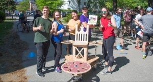
Overall, we had a great experience in this course. We learned about a wide variety of topics, gained experience in the machine shop, and worked well together as a group. The competition day was a fun way to close out a challenging project. Based on the reactions of spectators at the competition and other Thayer students who took the machine for a spin, we think that our vehicle could be a viable commercial product for a fun toy. It would be particularly fun in a setting with linoleum or poured concrete flooring.
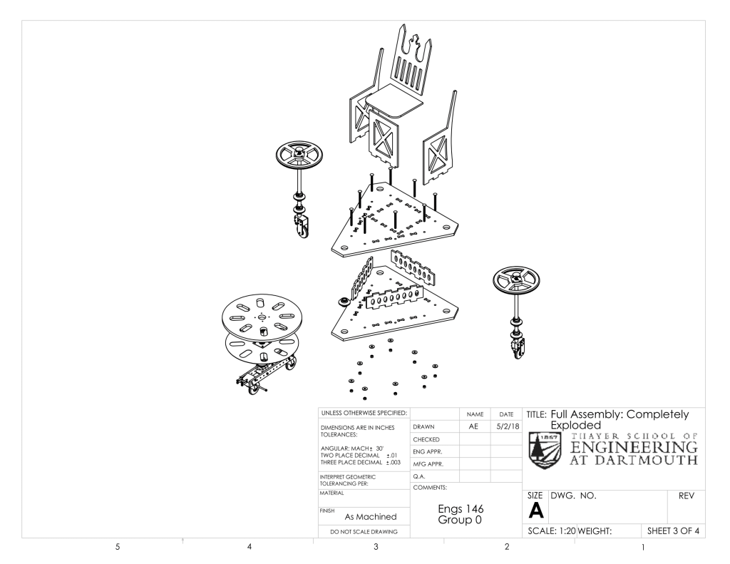
VIII. Drawings:
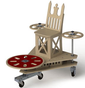
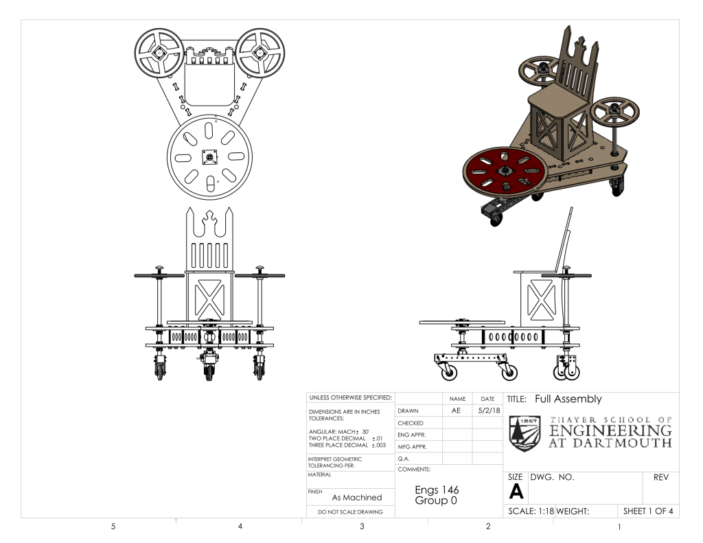
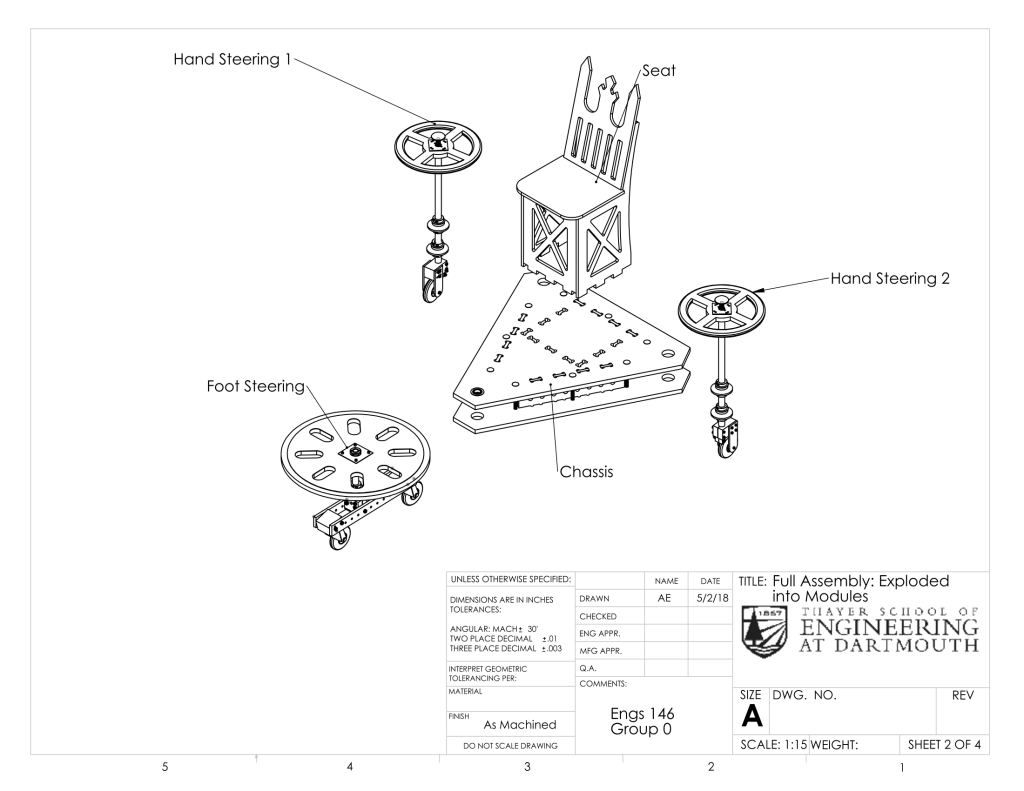
Full Assembly
Back to Top
Foot Steering Module


Back to Top
Hand Steering Module

Back to Top
Chassis Assembly


Back to Top
Chair

IX. Design Evolution:
Preliminary Sketches
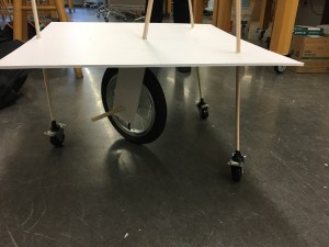
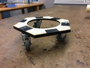
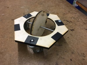
Conceptual Mock-Ups

Final Design Development