Challenge: Teams of 4-5 students (bot squads) design and fabricate Recycle-Bots to competitively collect four types of recyclables from a field. The bot that collects the most wins.
Required Bot Functions: movement, gathering, lifting, and releasing.
IV. Design Process (Specifications, Iterations, Analysis, etc.)
I. Final Design:
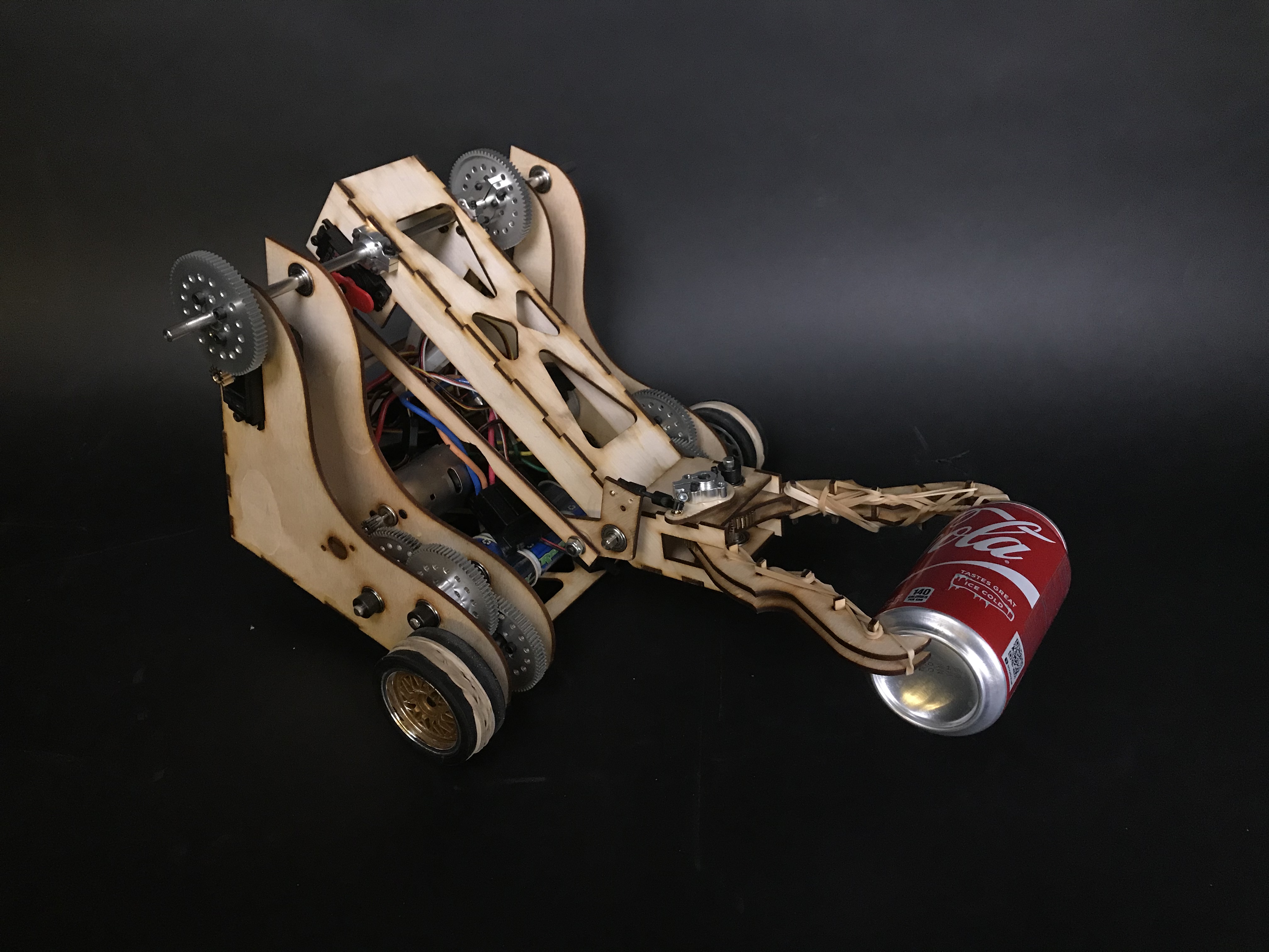
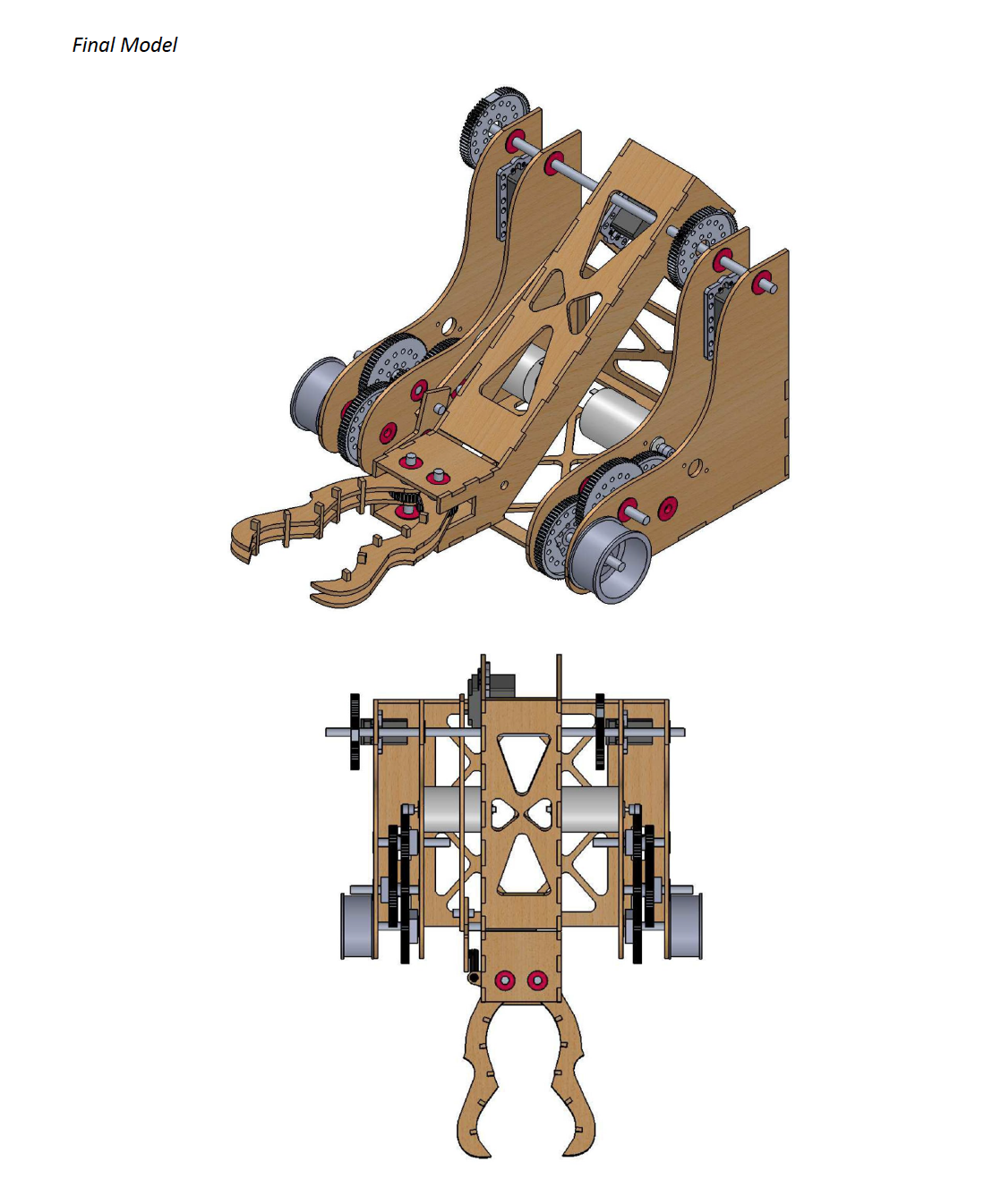
Our group strove for a simplistic design that would minimize stress put upon our claw and arm mechanism (as to prevent bot injury during competition) along with enabling fast maintenance during competition. Additionally, we geared down the drivetrain to enable smoother and more precise bot maneuverability while also utilizing a tractor style alignment of the motors to create a tighter turn radius.
-
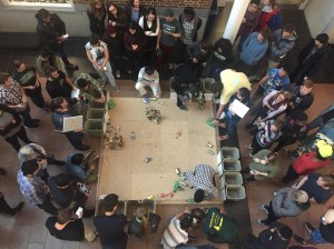
- Competition Arena

-

- Isometric View
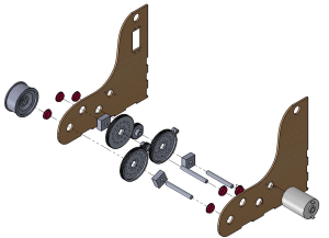
II. CAD / Assembly Process:
-

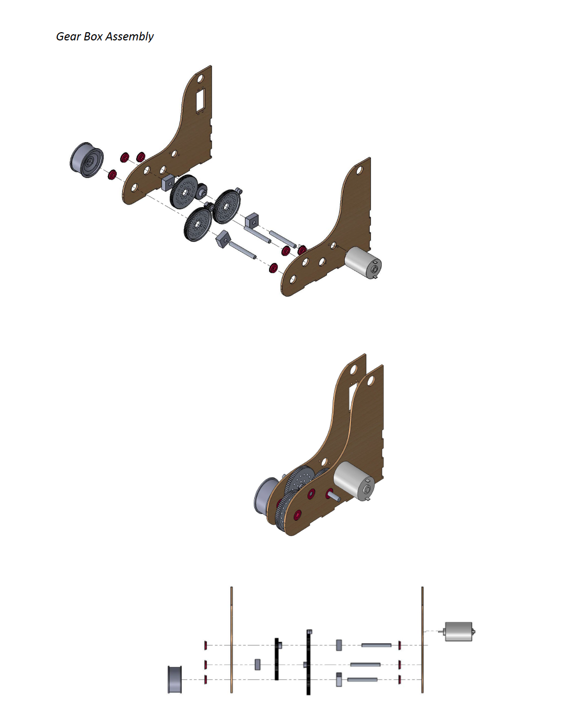
- Gear Box Assembly
-
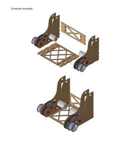
- Drivetrain Assembly

-

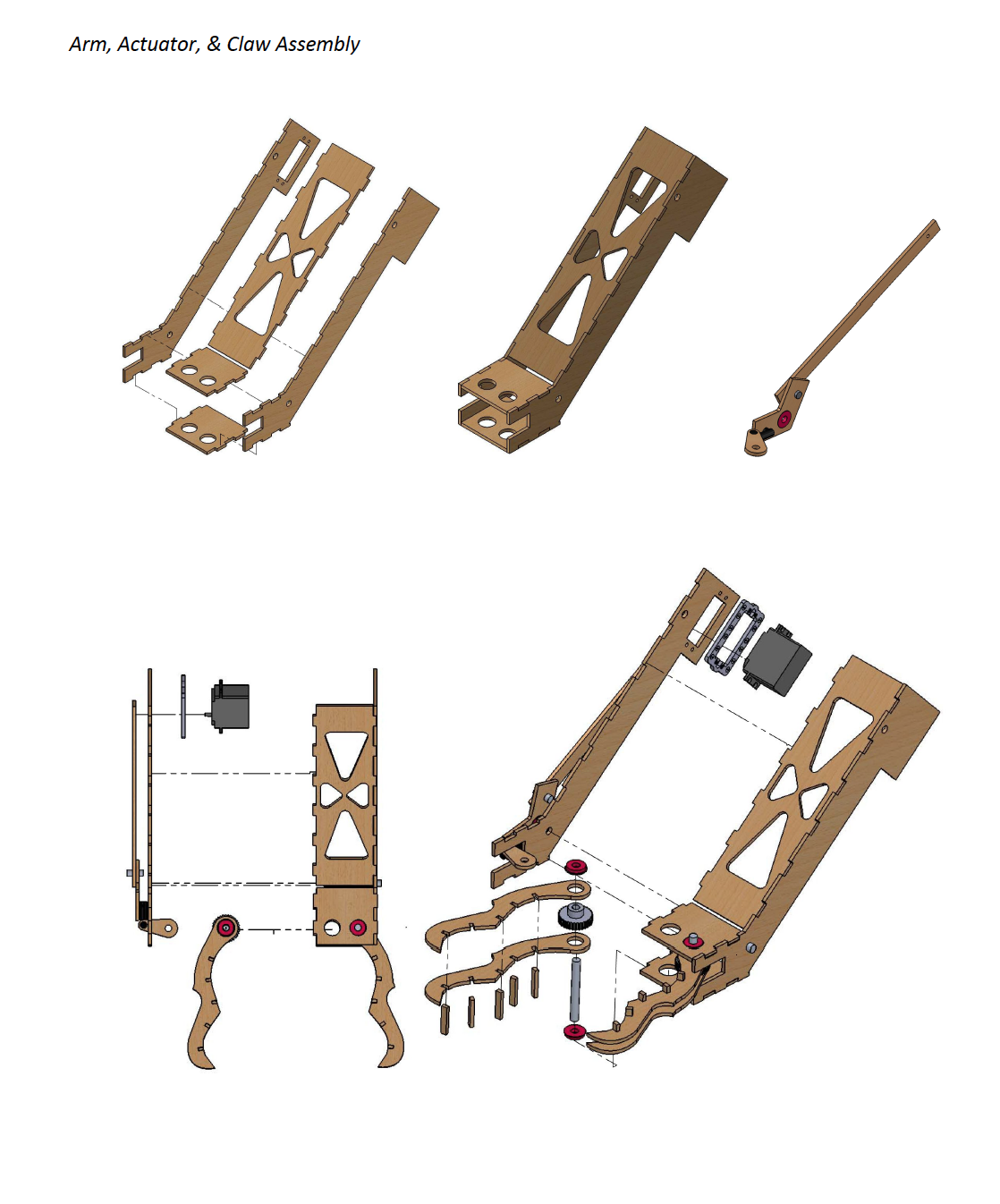
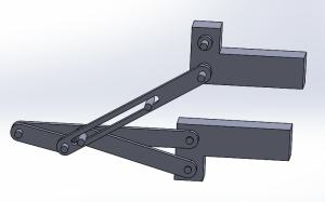
- Arm, Actuator & Claw Assembly
-

- Arm, Actuator & Claw Assembly
-

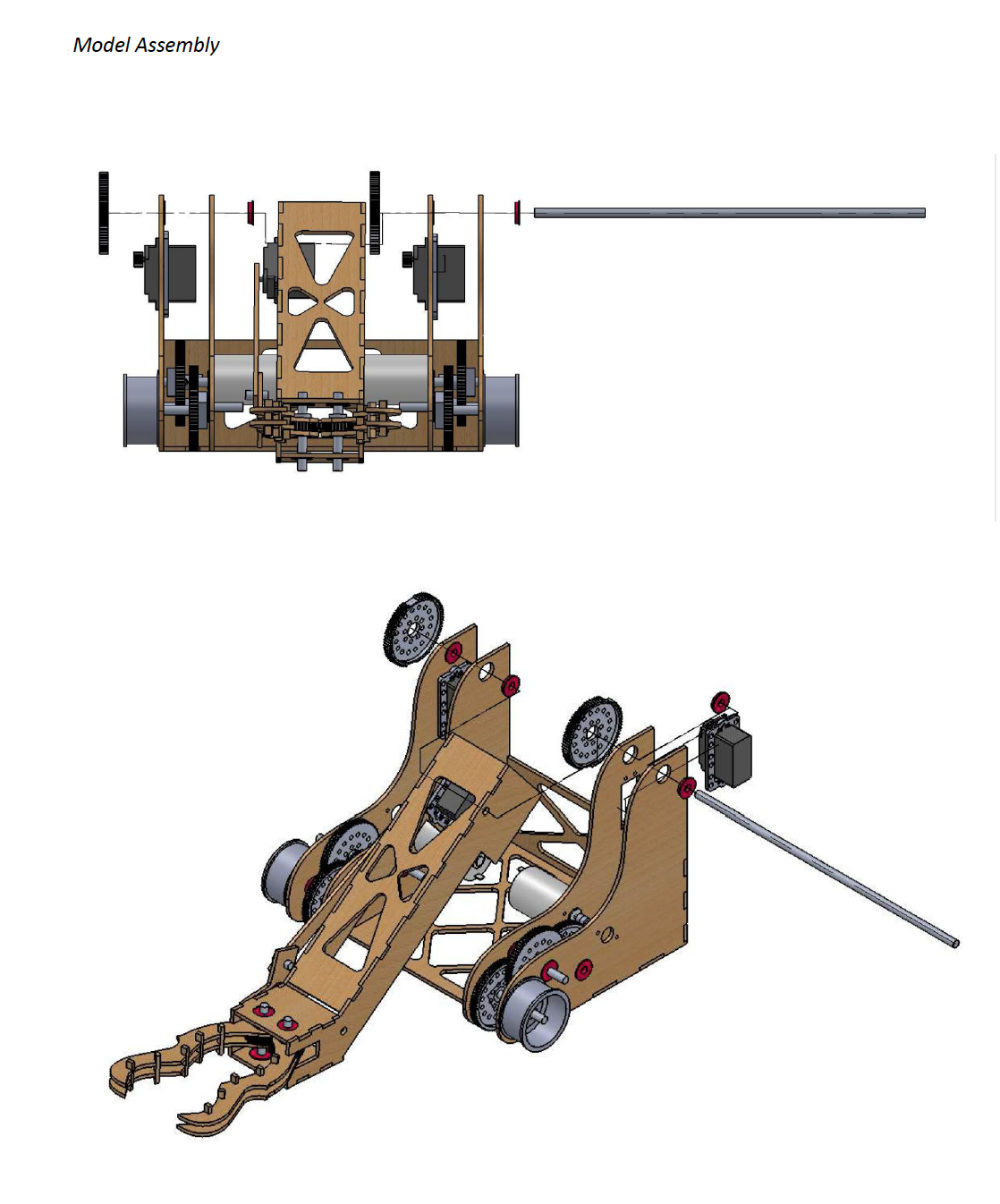
- Model Assembly
-

- Final Model
III. Performance Analysis:
Overall we were extremely pleased with how the bot turned out and its ability to put recyclables in the correct bins. The bot moved at the calculated rate and was able to lift all of the objects with ease. While all mechanisms performed well, one struggle we came across was collecting water bottles that were knocked over as opposed to standing upright. Consequently, we altered our strategy and collected water bottles first, prior to them being displaced from their starting position. Also, we were one of the only groups able to collect one of each type of recyclable (which garnered us bonus points). Moving forward we would add some design limits into the arm rotation so that it could not be over actuated by the operator. The video below is a time-lapse of our bot during competition (located in the bottom left part of the arena).
IV. Design Process (Specifications, Iterations, Analysis, etc.):
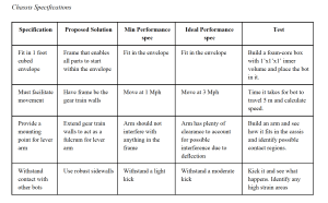
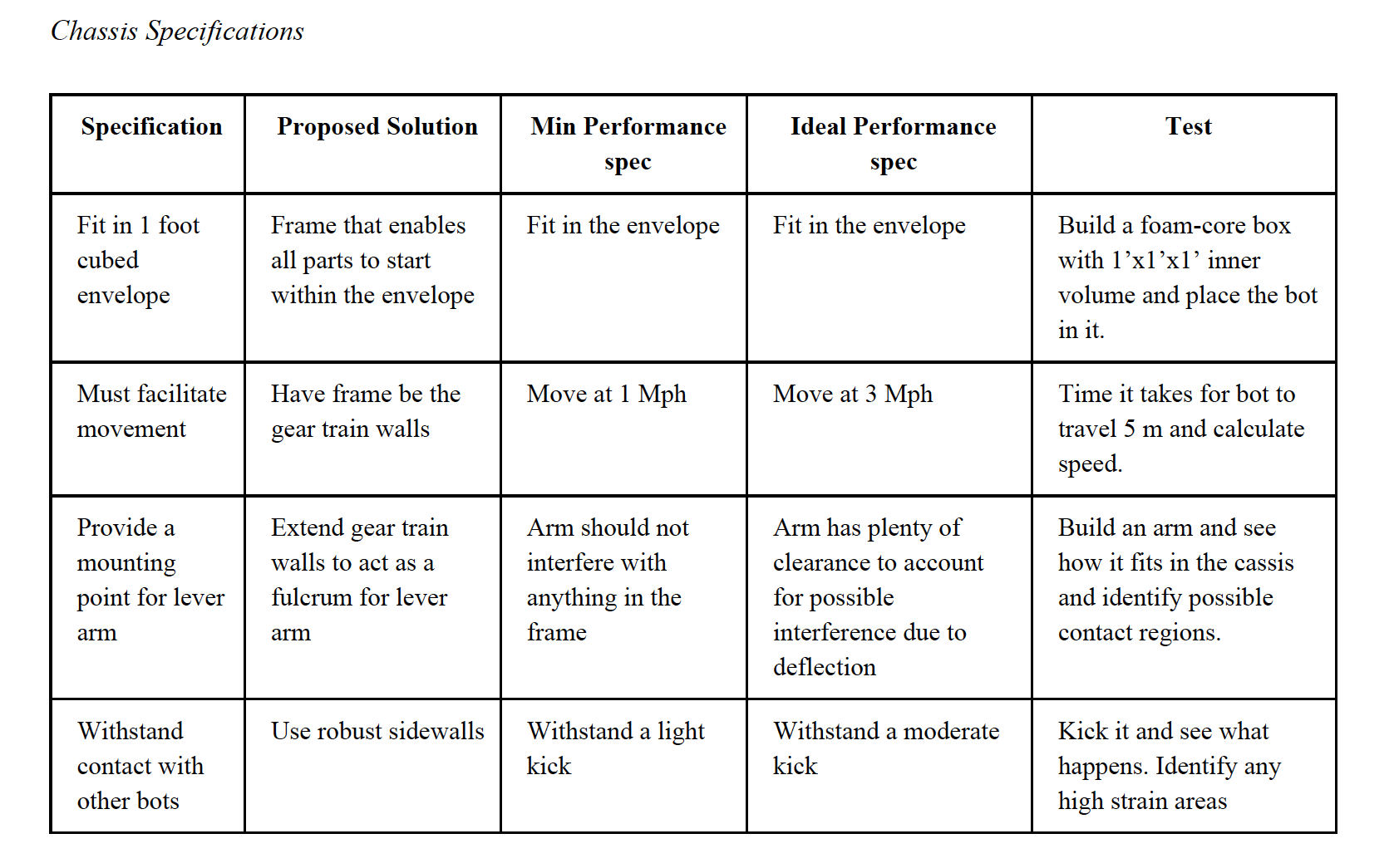
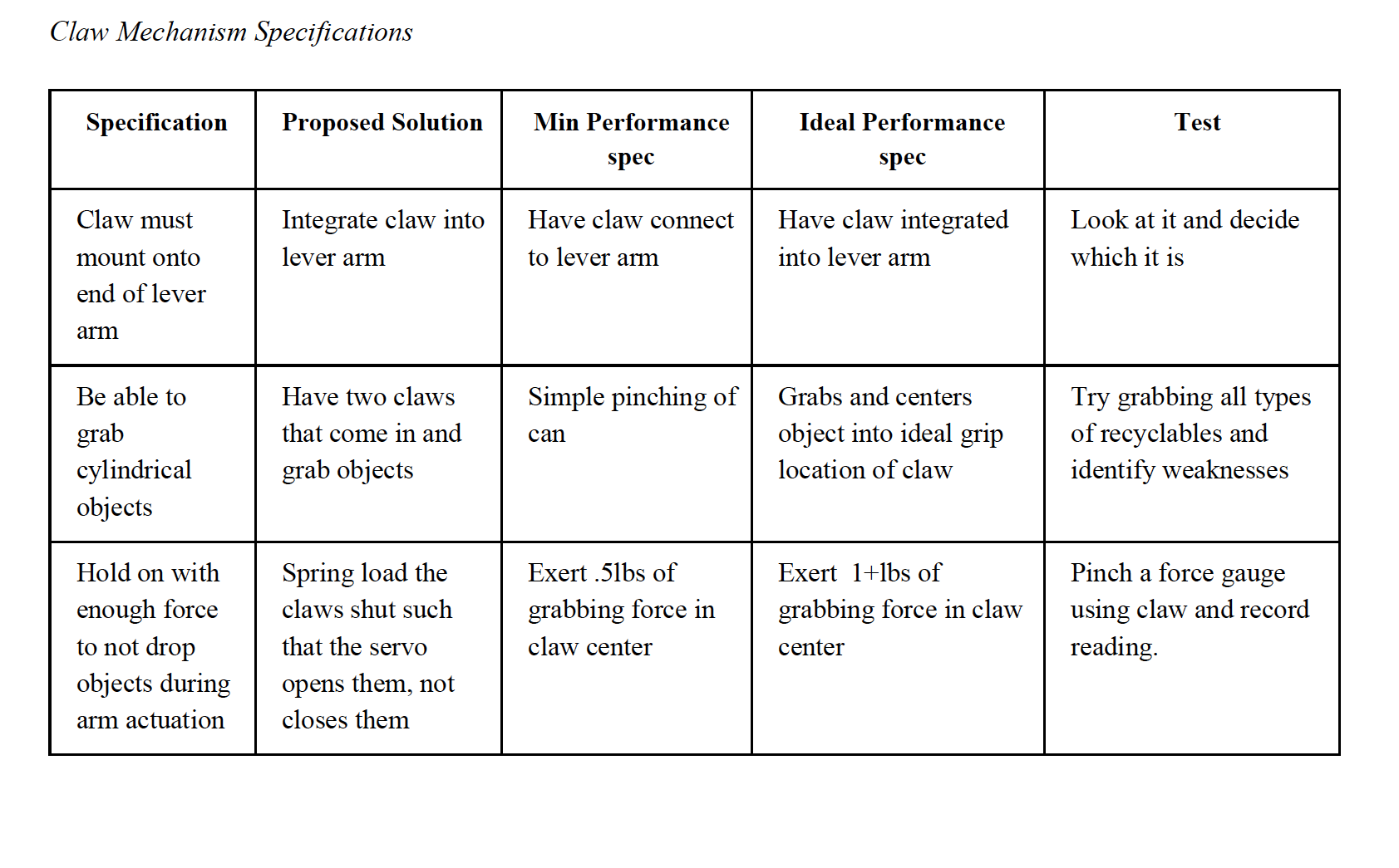
We broke the challenge into three specifications (specs): chassis specs for bot movement, lift specs for elevating recyclables, and claw specs for securing cans and bottles. Our requirements are listed in the tables below.
-
- Chassis Specs
-

- Claw Mechanism Specs
-
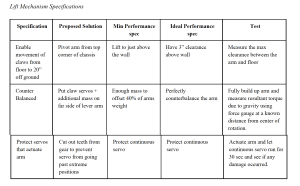
- Lift Mechanism Specs
Chassis
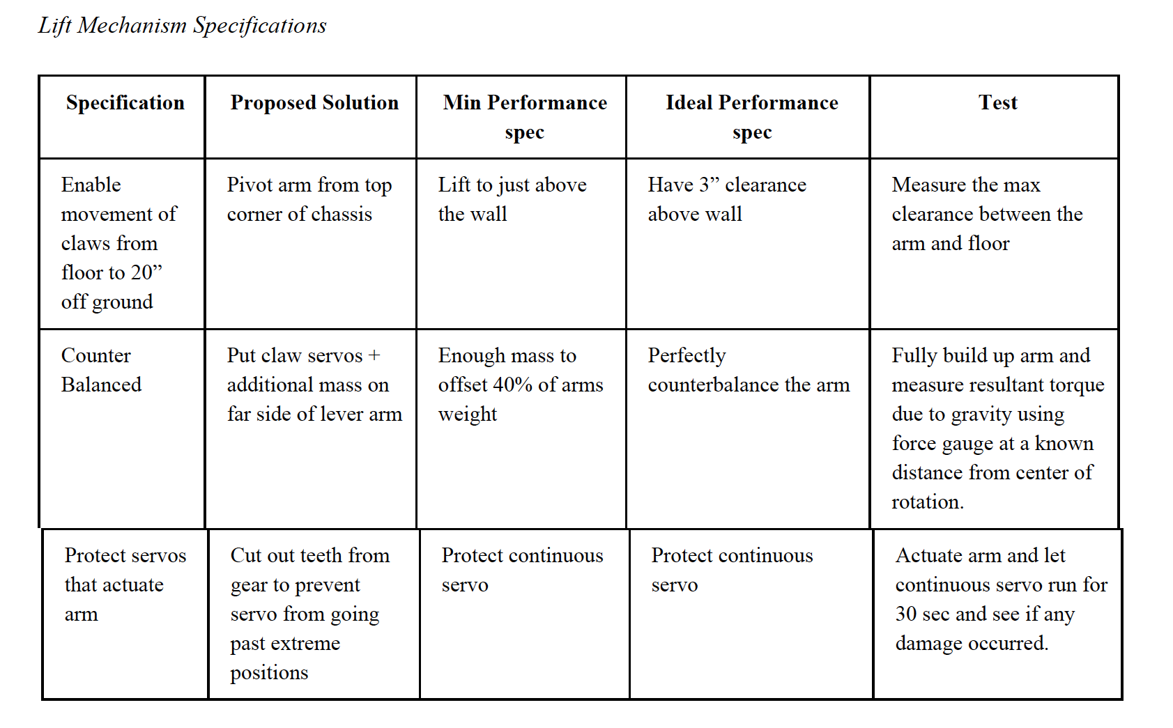
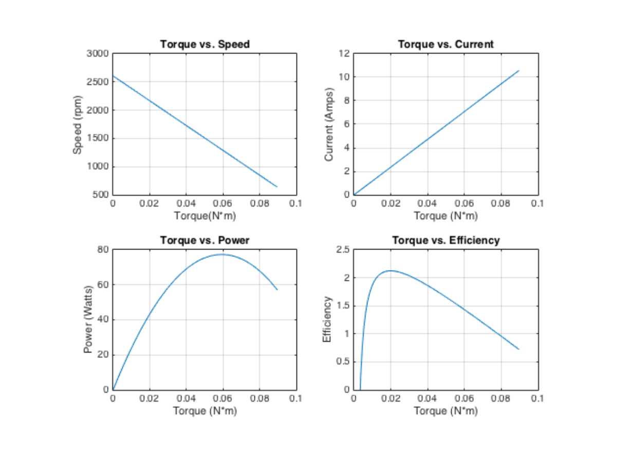
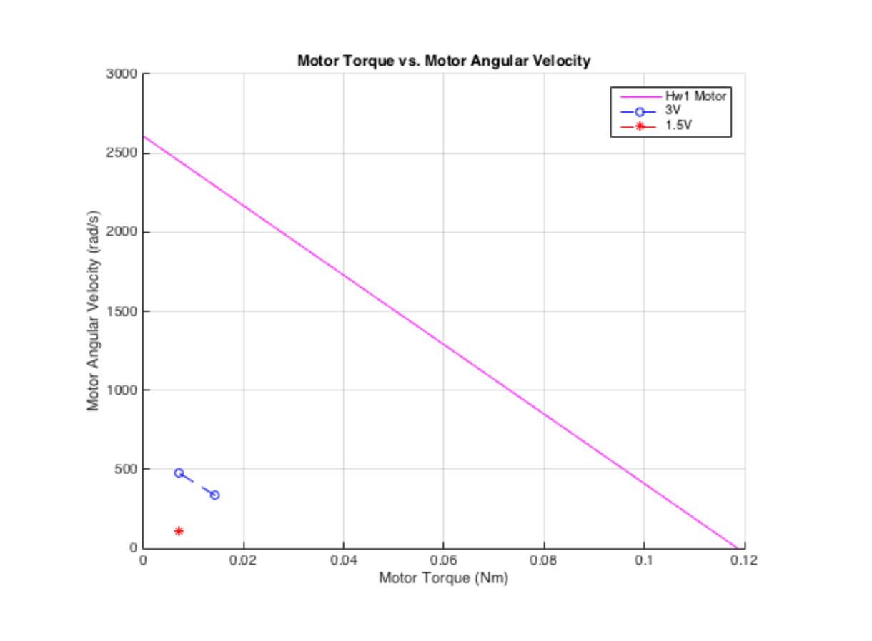
To determine the gear ratio for our drivetrain, we began by determining an ideal speed for our bot to move at through the arena (1 MPH would be most ideal as it is slow enough to accurately position the claw relative to the recyclables while still maintaining a competitive speed). Given this end objective, we determined what gear ratio would be needed so the motor could operate at peak efficiency while at this optimal speed. We calculated the required RPM at the wheel to be 134.454. This causes our 2.5” diameter wheel to move at approximately 1 MPH. Provided that the most efficient operating RPM of the motor is 15,980 (based partially on the MATLAB plots below), we then calculated that a gear reduction of 118.85 : 1 would be necessary (assuming 3.7 volt power source) to accomplish this objective.
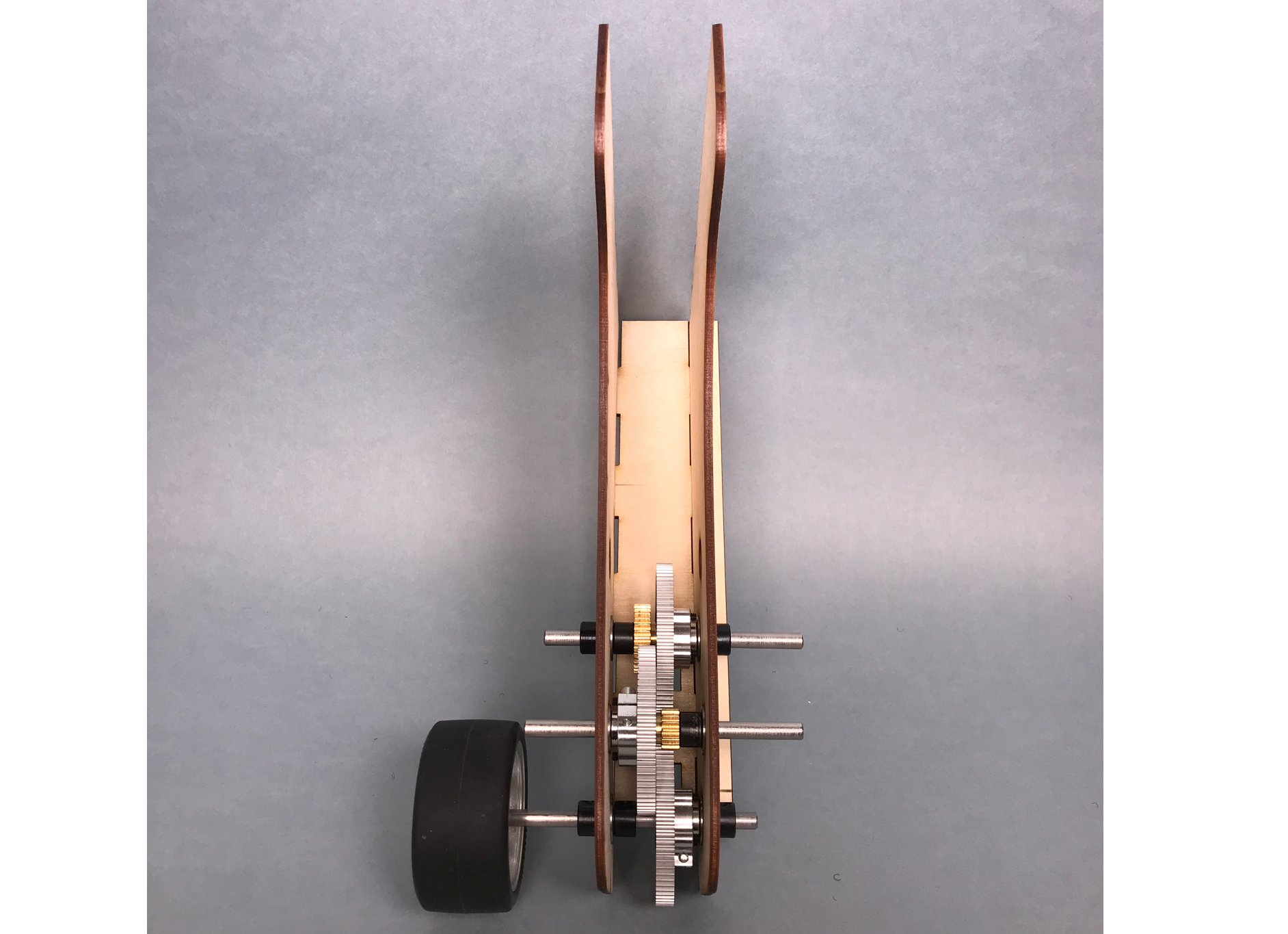
After verifying the available number of gears and mounting hardware, we came to the conclusion that a three step gear reduction of 10 : 72, 32 : 72, and 16 : 72 would provide the closest result to the desired reduction. This three step reduction provides us with a 72.9 : 1 reduction between the motor and wheels. Having calculated this ratio, we mocked up our drivetrain in SolidWorks then built one (of the two) sides to ensure that it operated properly. Once the gear train was spinning properly, we connected it to one of our motors and tested the output speed of the gearbox using the RPM rig provided to ensure we had a proper output speed. We measured the output RPM at ~200 and were satisfied that our design had met our specifications.
-
- Drivetrain Assembly

-
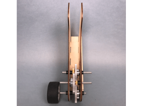
- Drivetrain Assembled
Claw & Lift Mechanisms
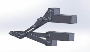
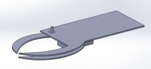
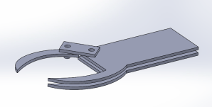
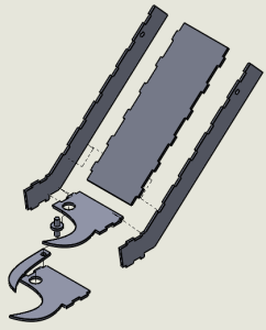
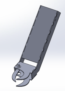
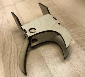
In the design phase, we started with a claw that only had one moving part to decrease complexity. Initially a parallel motion claw was decided upon (first and second iterations below). This preliminary concept focused on using a fixed middle support beam paired with an adjustable upper arm. The operation of the claw was hoping to rely on a servo with range of motion restricted by a cut slot. Additionally, a simplistic arm was created to help attach the claw to the robot’s body. However, maintaining a consistent parallel position amongst the two claws posed a substantial design issue and prompted iteration. The third and fourth iterations worked better than the prior versions but required too much material and lacked grip security. This led to further evolving our design. After laser cutting the fifth iteration, we had trouble grabbing smaller cans, prompting another redesign. The biggest change consisted of having two moving parts via connected gears as to increase the grabbing range and grip security of the bot. Upon the sixth-iteration, we created our final design which featured two grabbing zones, a concept influenced by the claws of a beetle (making its grip more versatile). When we laser cut this final iteration, we found that it could in fact grab upright cans and bottles easily, and even pick up cans that were lying on their sides. In competition, we wrapped rubber bands around the claw’s planks to increase friction/grip strength. Attaching the claws to gears simplified the actuation provided by a Bell crank attached to a 180 degree servo mounted at the top of the arm. The mounting of the servo had the dual purpose of counterweighting the arm. Using linkages and ball joints from the RC car’s suspension system (provided), we were able to transfer the motion from the servo linkage, through the crank, to a piece mechanically attached to the claw shaft. If we redesigned the claw one more time, we would probably cover the claws in plasti dip to increase the grip further.
-
- First Iteration
-
- Second Iteration
-
- Third Iteration
-
- Fourth Iteration
-
- Fifth Iteration Assembly
-
- Fifth Iteration Assembled
-
- Laser Cut Fifth Iteration
-
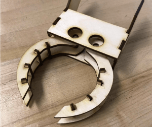
- Sixth Claw Iteration
-
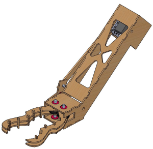
- Seventh Iteration of Claw & Arm
-
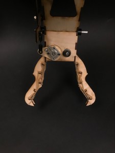
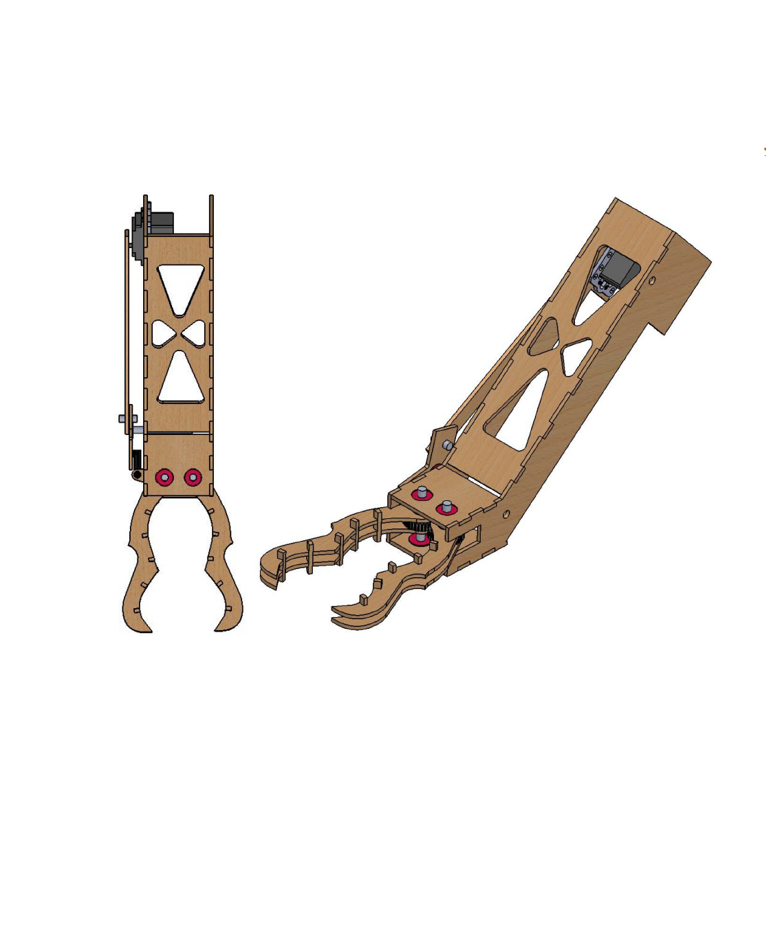
- Zoom on Claw
-
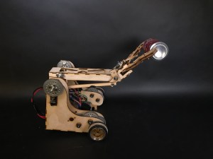
- Side View
-
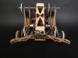
- Front View
To calculate the required torque to rotate the arm, we assigned the claw arm materials and calculated the mass in Solidworks to be 0.13 pounds. Next, we decided the heaviest load would most likely be the larger plastic bottle which weighs approximately 0.02799lbs. With the fulcrum 10 inches from the load of the claw, a simple torque calculation gave us (10/12)inches * 0.158lbs = 0.132 ft*lbs. One servo was rated 30 to 38.8 in*ounces which converted to 0.202 ft*lbs. With the 6:1 gear ratio and dual servos, we effectively had 12 times this torque which was more than sufficient to lift the arm and load.
